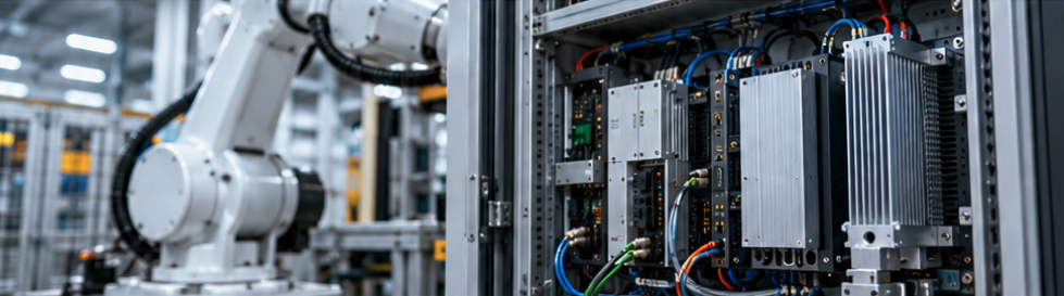
Industrial robots are becoming more compact, more capable, and more dependent on electronics. A modern robotic system may combine servo drives, power converters, motion controllers, sensors, and onboard computing hardware within a limited amount of space.
Each component performs a different function, but they share one engineering challenge: heat.
For robot manufacturers and automation system integrators, thermal management is not simply a matter of preventing electronic components from overheating. It can influence equipment reliability, packaging flexibility, maintenance requirements, and the ability to operate consistently under demanding production conditions.
The challenge is particularly important in compact servo drives, sealed robotic controllers, and autonomous mobile robots (AMRs), where available space and cooling airflow may be limited.
A heat sink that performs adequately on a laboratory bench may behave quite differently after installation inside a densely packed industrial enclosure.
Why compact robotic systems create difficult cooling conditions
Traditional industrial automation systems often separate power electronics, control hardware, and mechanical equipment into different assemblies. Compact robotic systems may bring many of these functions closer together.
Servo drives generate heat through semiconductor switching and conduction losses. Power supplies and DC/DC converters introduce additional losses, while processors, communication modules, and machine vision hardware contribute their own thermal loads.
In an industrial control cabinet, these components may share an elevated internal air temperature. In a mobile robot, they may be installed inside a relatively small chassis with limited ventilation.
The resulting challenge is not necessarily an unusually high heat load from one component. It is the combination of multiple heat sources, restricted airflow, and limited space for effective heat dissipation.
Engineers therefore need to evaluate thermal performance at the system level rather than treating each electronic component independently.
Start with actual operating conditions, not just rated power
One of the most important distinctions in robotic thermal design is the difference between electrical power consumption and heat dissipation.
A motor drive rated for substantial electrical output does not convert all that power into heat. Its thermal load comes primarily from losses in the power semiconductors and other components.
Those losses depend on factors such as operating current, switching frequency, device characteristics, and the robot’s duty cycle.
A robotic arm performing intermittent pick-and-place operations may experience repeated peaks in motor current followed by periods of lower demand. A conveyor drive or continuously operating servo system may produce a different thermal profile.
For short-duration loads, the thermal mass of the components and heat sink can temporarily absorb energy. However, this does not eliminate the need to evaluate steady-state temperatures or repeated operating cycles.
A useful thermal design review should consider three conditions:
- Peak loading: The maximum heat generation during demanding movements or operating events.
- Sustained loading: The losses associated with continuous operation over longer periods.
- Repeated duty cycles: The temperature response when heating and cooling periods occur repeatedly.
The most demanding thermal condition is not always the moment of highest instantaneous electrical load.
Calculate the thermal budget before choosing the heat sink
Heat sink selection should begin with a temperature budget.
In a simplified steady-state analysis, the allowable thermal resistance between the heat sink base and the surrounding cooling air can be estimated from the available temperature difference and the heat to be dissipated.
For example, consider an illustrative motor-drive assembly with the following conditions:
- Heat dissipated into the heat sink: 45 W
- Local cooling air temperature: 35°C
- Maximum permitted heat sink base temperature: 65°C
The available temperature difference is 30°C. Dividing this by the 45 W heat load gives an allowable effective base-to-air thermal resistance of approximately 0.67°C/W.
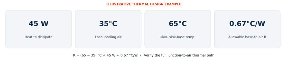
This is an illustrative first-pass calculation, not a complete thermal design.
The semiconductor junction temperature must still be evaluated through the complete thermal path, including junction-to-case resistance, the thermal interface material, and the heat sink. Additional heat sources, airflow restrictions, and transient behavior also need consideration.
Nevertheless, this approach provides a more meaningful starting point than choosing a heat sink solely by its external dimensions or fin count.
A fan does not guarantee effective cooling
Forced-air cooling is common in industrial electronics, but its effectiveness depends on the airflow that actually reaches the heat sink.
A fan may have an impressive free-air airflow rating. Once installed inside an enclosure, however, the airflow must pass through filters, ventilation openings, cables, electronic assemblies, and heat sink fins.
Each restriction adds resistance to the airflow path.
Closely spaced fins can increase heat-transfer surface area, but they may also increase pressure drop. If the selected fan cannot provide sufficient pressure, the additional fin area may deliver little practical benefit.
This creates a tradeoff between fin density and available airflow.
For natural-convection systems, the situation is different. Without a fan, heat removal relies significantly on buoyancy-driven air movement. Fin orientation, channel spacing, and clearance around the heat sink become especially important.
The same heat sink profile should not automatically be considered suitable for both passive and forced-air cooling.
Engineers should also consider how dust accumulation, partially blocked filters, or reduced fan performance may affect the system during its operating life.
For enclosed robots and industrial controllers, the relevant cooling environment is the air surrounding the heat sink inside the equipment, not necessarily the ambient temperature outside the machine.
The mounting surface is part of the thermal design
Even a well-designed heat sink can underperform if the mechanical interface with the power module is inadequate.
Heat must travel from the semiconductor package or module baseplate through the thermal interface and into the heat sink.
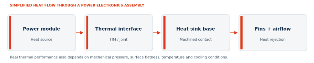
Small surface irregularities, excessive gaps, burrs, or inconsistent mounting pressure can increase thermal resistance.
Thermal interface materials help fill microscopic gaps, but they should not be treated as a substitute for appropriate mechanical design.
For IGBT, MOSFET, and SiC power modules, the required mounting-surface flatness, surface condition, and fastening method should be determined from the relevant module manufacturer’s specifications.
This is particularly important for large mounting areas and applications involving multiple power modules on a common cooling base.
From a manufacturing perspective, aluminum extrusion provides a practical foundation for many industrial heat sinks, but critical contact areas may still require precision CNC machining.
Manufacturers such as XINXIANG produce heat sinks for power electronics using different manufacturing methods and secondary machining operations to accommodate module layouts, mounting requirements, and cooling conditions.
The key consideration is that mounting-surface specifications should be defined before production rather than treated as an inspection issue at the end.
Choosing a manufacturing process for compact cooling hardware
Different robotic systems require different approaches to heat sink manufacturing.
Extruded aluminum heat sinks are often a practical starting point for servo drives, industrial controllers, and power supplies. They combine a continuous fin-and-base structure with relatively economical production, particularly when suitable tooling already exists.
Skived heat sinks can provide closely spaced fins and a one-piece fin-and-base structure. They may be worth evaluating when a compact design requires increased surface area and the available airflow can support the fin geometry.
Bonded-fin heat sinks offer another option when the required dimensions or fin arrangements are difficult to achieve with conventional extrusion.
Liquid cold plates may be considered when the heat load, installation constraints, or system architecture make air cooling impractical. However, their use also introduces requirements for coolant circulation, sealing, connections, and maintenance.
There is no universally superior method.
For mobile robotic systems, mass and packaging can be especially important. For stationary automation equipment, production cost, long-term reliability, and ease of maintenance may carry greater weight.
The correct manufacturing process should emerge from the thermal and mechanical requirements, not the other way around.
Existing extrusion tooling can simplify development
A fully custom heat sink is not always necessary.
During the early stages of a robotics project, engineers may be able to select an existing aluminum extrusion cross-section that fits the available cooling envelope.
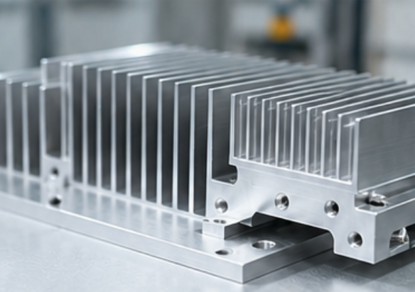
Reviewing existing aluminum heat sink extrusion profiles can help identify potential starting geometries based on width, overall height, and base thickness.
An existing extrusion can often be cut to the required length and further customized through CNC machining.
Mounting holes, threaded features, slots, pockets, and clearance areas can be added according to the mechanical design.
This approach may reduce tooling requirements and development time compared with creating a completely new extrusion die.
However, the existing cross-section still needs to be checked against the thermal design. Matching the available space does not establish that a profile provides sufficient cooling.
If the required fin arrangement or base geometry differs substantially from available profiles, custom tooling or another manufacturing method may be the more appropriate choice.
Validate the complete assembly under realistic conditions
Thermal simulation and component specifications are valuable design tools, but prototype testing remains important.
A heat sink that meets a calculated thermal-resistance target may still perform differently when installed beside other heat-generating components.
For robotic equipment, useful validation conditions include:
- Maximum expected operating temperature inside the enclosure
- Representative motion and motor-loading cycles
- Sustained high-duty operation
- Normal and reduced cooling airflow
- Heat generated by neighboring electronic assemblies
- Actual mounting hardware and thermal interface materials
Temperature measurements should be taken at relevant component locations, with particular attention to the relationship between the measured points and the semiconductor junction temperatures that must remain within specification.
Where possible, testing should use the intended production assembly rather than a loosely mounted laboratory configuration.
Vibration, thermal cycling, and mechanical loading may also need to be considered when evaluating long-term interface stability.
Bring thermal and manufacturing teams into the design process earlier
Thermal management becomes more difficult and expensive to change once the enclosure dimensions, PCB arrangement, and mounting features are fixed.
Early communication between electronics engineers, mechanical designers, and heat sink manufacturers can help identify limitations before tooling and production commitments are made.
For a useful manufacturing review, the project team should provide the estimated heat dissipation, cooling environment, available dimensions, mounting layout, required surface tolerances, material preferences, and expected production quantity.
These details help determine whether an existing extrusion, a custom heat sink, or a different cooling architecture is appropriate.
The objective is not simply to manufacture a metal component that fits the drawing. It is to produce a repeatable cooling solution that works with the complete electronic and mechanical assembly.
Thermal reliability starts with practical design decisions
As industrial robots become more compact and electronics-intensive, effective thermal management requires closer attention to the relationship between power losses, airflow, mechanical interfaces, and manufacturing processes.
The most effective solution is not necessarily the heat sink with the largest number of fins or the most complicated construction.
It is the solution that maintains acceptable component temperatures under realistic operating conditions while meeting the equipment’s space, weight, reliability, and production requirements.
For robot builders and automation system integrators, addressing these details early can help prevent thermal problems from becoming costly redesigns later in development.
Main image: An industrial robot beside a power-electronics control cabinet.
