Qualifying SLS PA12 Robot Tooling Before it Enters a Production Cell
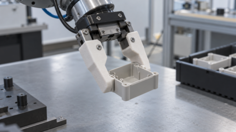
A robot gripper can look convincing on a CAD screen and still fail its first week on the line. A fingertip may slip on a slightly different part finish.
A printed bracket may flex enough to move a sensor out of position. A mounting hole may be nominally correct but leave too little room for a screw head, insert, or cable.
These are not abstract material questions. They are integration questions, and they matter most where a custom component meets a moving robot, a real workpiece, and an operator’s production target.
Selective laser sintering (SLS) in PA12 nylon is useful for many custom end-effector components because it can produce intricate shapes without the support structures associated with some other printing processes.
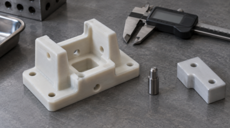
It is especially attractive when a team needs to iterate a finger profile, route a vacuum passage, or combine several locating features in one part.
Yet the decision to print is only the start. The more important decision is how to qualify the printed component for its actual job.
Start with the robot task, not the material brochure
Define what the component must do before choosing a process. Is it a non-contact cover, a nest that holds a stationary workpiece, or a gripper finger that repeatedly accelerates a payload?
The answer changes the relevant loads and failure modes. Record the part mass, expected acceleration, contact area, cycle frequency, likely collisions, cleaning routine, and the environment around the cell.
A gripper that works in a dry demonstration may behave differently near oil mist, abrasive dust, or elevated heat.
Separate safety-critical functions from convenience features. A printed cable guide may be easy to revise; a part that retains a heavy payload or acts as a machine guard needs a more formal engineering review.
If failure could injure someone or damage equipment, the integrator should apply the appropriate machine safety process and validate the complete system. A material data sheet alone cannot establish fitness for that use.
Where SLS PA12 fits – and where it needs help
SLS PA12 can be a sensible candidate for custom fingers, sensor mounts, alignment nests, and low-volume fixtures when geometry, weight, or revision speed matters.
Its design freedom can make space for a workpiece contour or a protected routing path. The term sls nylon pa12 describes a material and process family, however, not a universal property set.
Powder specification, build settings, orientation, post-processing, and the requested finish can all affect the delivered part. Ask the supplier which grade and process controls apply to the order.
Do not make every interface polymer merely because the body is printed. Metal inserts, bushings, or plates may be appropriate at threads, bearings, locating surfaces, and heavily loaded connections.
Conversely, some applications may call for machined metal, another polymer, or a hybrid assembly from the outset. Temperature exposure, chemicals, sustained loading, friction, and dimensional stability should be assessed against the actual service conditions.
A prototype that survives a few dry cycles is not proof that it will hold tolerance over a production shift.
Design the load path through the whole assembly
Follow the force from the workpiece contact point through the finger, its fasteners, the gripper body, and the robot flange. A narrow neck may be convenient for access but may also concentrate stress or allow deflection.
Add material where the load path needs it, use generous transitions where geometry permits, and avoid treating a nominal CAD wall as an assured minimum after manufacturing and finishing.
For a long, slender finger, stiffness and positional repeatability may matter more than whether the part visibly breaks.
The mounting interface deserves the same attention as the visible contact profile. Specify datums, fastener access, clearance for tools, and whether alignment relies on a screw, dowel, shoulder, or mating feature.
If an insert is planned, define its type and installation method before finalizing the hole. For a sensor mount, consider the sensor’s adjustment range and cable bend radius.
For a vacuum tool, make the channel accessible enough to remove residual powder and inspect the passage. A clever enclosed route is of little value if it cannot be cleaned or verified.
Identify the dimensions that actually control the robot operation: gripping span, finger parallelism, sensor position, mating-hole pattern, and clearance to nearby tooling.
Communicate these as critical-to-function features rather than assigning a tight tolerance to every cosmetic surface.
The supplier can then discuss build orientation, finishing, inspection, and whether a secondary operation is needed for a particular interface.
Use a staged qualification sequence
A useful first article is a test object, not merely a sample to photograph. Inspect the delivered component for damaged edges, trapped powder, blocked channels, and fit at the intended mating surfaces.
Record the part revision and build information supplied with it. Assemble it on the end effector and check access to screws, air fittings, and sensors before asking the robot to move.
Then increase the challenge in controlled stages. Begin with an unloaded motion check at reduced speed and verify clearances across the full path.
Add a representative workpiece and observe pick, transfer, and release, including the least favorable orientation. Increase speed and payload only within the validated machine setup.
Track slip, positional drift, contact marks, fastener loosening, and any permanent deformation. If the cell handles multiple part variants, test the limits of that variation instead of only the easiest sample.
A short cycle trial can reveal installation mistakes; it cannot establish long-term durability by itself.
Set a test duration that reflects the use case, define acceptable wear and repeatability before testing, and remeasure the critical features afterward.
If the tool will see coolant, cleaning agents, heat, or repeated manual handling, include those exposures in the plan.
Document both the pass criteria and the conditions that would trigger a redesign. This makes the next revision a response to evidence rather than guesswork.
Plan for replacement and change control
A robot cell rarely uses one custom finger forever. Spares, revised workpieces, and maintenance all create opportunities for dimensional drift.
Keep the approved CAD revision, drawing, material callout, post-processing requirements, inspection points, and assembly instructions together.
If the part is ordered again, compare a new unit against the approved interface and functional dimensions before installing it.
The same applies after a supplier, powder grade, finishing method, or build orientation changes.
Think about serviceability while the design is still flexible.
Can a technician replace one finger without disturbing the other side? Is there a visible mark or datum that prevents reversed installation? Can worn contact pads or inserts be replaced without discarding the whole assembly?
These questions turn a printable component into maintainable production tooling. They also help the purchasing team understand which details must remain fixed and which can evolve.
Give the supplier a useful engineering brief
A quotation request should include more than an STL file and a quantity. Send the CAD model, a drawing or marked screenshot of critical interfaces, expected use, approximate load and cycle conditions, surface-contact concerns, and the number of units needed for both testing and spares.
Call out any mating hardware, insert requirements, channels that must be clear, and surfaces that need inspection.
State what is known and what still needs engineering discussion; that is more useful than inventing a tolerance for every feature.
For teams considering a nylon 3d printing service, the material overview from JCProto is one starting point for discussing SLS options and the manufacturability of a specific design.
The supplier should confirm the available PA12 grade, process, finishing choices, inspection plan, and any application-specific limitations for the proposed part. An engineering review and cell-level validation remain necessary before production use.
The decision is about evidence
SLS PA12 can help robotics teams iterate shapes that are awkward to make by conventional methods, but geometry alone does not make a reliable end effector.
The strongest projects connect the printed part to a defined task, a clear load path, inspectable interfaces, measured trials, and a controlled replacement process.
That evidence tells the team when the design is ready to run, when it needs a revision, and when a different material or manufacturing route is the better choice.
