Software projects mainly include various components, complicated structures, and multiple processes that can’t be done without planning.
Here comes the need for visual representation, which helps developers and team members understand how a system should work.
Unified Modeling Language (UML) diagrams offer easy-to-understand visual ways to explain software structures and associated interactions.
UML diagram templates make it easier for teams to create these models for diverse software needs. Developers can use these samples when they plan architectures, explain requirements, document systems, and review software interactions. This article covers 8 common uses of UML templates in software projects.
Readers can understand where these templates fit and how they support better software planning.
1. When You Need Planning and Designing for Software Architecture
Software teams use UML templates to plan how an application should look before development begins. These templates show how different parts of the system connect and work together. Class and component diagrams make it easier to explain system structures and relationships.
According to PMI’s Pulse of the Profession 2024 report, the average project performance rate among respondents was 73.8%, highlighting the importance of choosing a suitable approach.
Organizations lose resources when projects lack proper planning and clear requirements. With a clear visual plan, software projects can move forward with better direction.
Steps to Use These Templates for Software Architecture Planning
- Define the main system components: Identify the key parts of the software, such as modules, classes, or services.
- Show connections between components: Use UML illustrations to explain how different parts communicate and depend on each other.
- Review the system structure: Check the diagram to find missing elements or possible design issues before development starts.
2. Analysis of User Requirements and System Function Mapping
UML design templates help teams understand what users expect from a software application. Use case diagrams show user actions, system responses, and important features within the software. These visuals make it easier for developers to understand how people interact with different functions.
As a result, teams can focus on building features that users actually need. Clear requirement mapping creates better communication between stakeholders and developers. It connects user expectations with the final software goals in a simple way.
3. Visualization of Class Relationships and Software Components
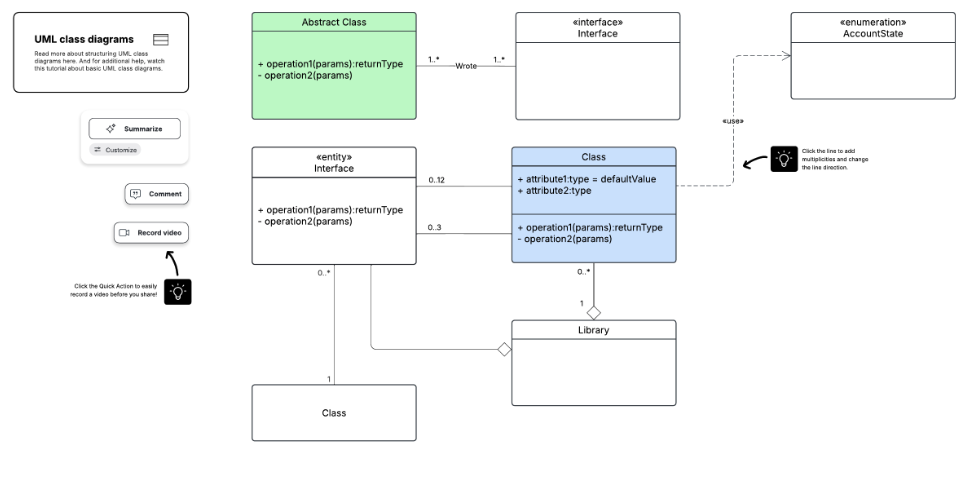
Software applications include different classes, objects, and components that work together behind the scenes. UML templates help developers show these connections through simple visual illustrations. Class diagrams explain object relationships, while component frameworks show larger system connections.
Common UML Diagrams Used in this Case
Class Framework
It shows the structure of classes, their attributes, methods, and relationships within a software system.
Component Diagrams
It explains how different software components connect and interact with each other.
Object illustrations
It provides a snapshot of objects within a system and shows how they relate at a specific point.
Package Diagrams
It displays how related classes and components are grouped to create a better-organized system structure.
4. Reference Creation and Software System Documentation
UML diagram samples help teams create visual records of software structures and processes. These samples explain how different parts of an application work without relying on long written documents. Teams can use them when reviewing existing systems or sharing technical details.
Good documentation becomes useful when projects need updates or new developers join the team. UML templates make system details easier to find and understand later. They also help teams maintain a clear picture of the software throughout its lifecycle.
Typical Issues Solved Through Better Documentation
Here are the common problems that UML documentation can help solve:
- Complex system understanding: Makes software structures easier to review and explain.
- New developer onboarding: Helps new members understand systems faster.
- Update-related confusion: Shows connections before making software changes.
- Missing system details: Keeps important information organized and accessible.
- Poor team communication: Creates a shared view of software functions.
5. Representation of Processes and Methods
Software teams use UML templates to explain how tasks move through different stages within an application. Activity diagrams show actions, decisions, and possible paths that users or systems follow. This makes complex processes easier to understand before developers build the final solution.
Teams can review these models to understand how different activities connect with each other. They can also find areas where processes may need changes or improvements. A clear activity structure gives developers better knowledge of how the software should respond.
6. When Communication Mapping and Object Interaction are Required
Software systems contain different objects that exchange information to complete specific functions. UML templates show how these objects communicate during different actions within an application. Sequence diagrams explain the order of messages shared between different system elements.
These models make complicated interactions easier for developers to review and understand. They provide a clearer picture of how software parts respond to different requests. This allows teams to create smoother connections between various elements of the system.
7. Visualization of Software Deployment Strategy
Software teams use UML templates to understand how applications connect with technical environments. Deployment diagrams show where software components operate and how different systems communicate with each other. This gives developers a better view of the required setup before launch.
These visual representations are useful when teams plan infrastructure or manage complex applications. They show the relationship between hardware, software, and network elements. A proper deployment view helps developers maintain a more organized system environment.
Examples of Complex Applications That Use Deployment Method
Here are some examples where deployment planning becomes important:
- Banking applications: Manage secure connections between servers, databases, and user platforms.
- Healthcare systems: Organize patient data systems, applications, and connected devices.
- E-commerce platforms: Manage websites, payment systems, databases, and backend services.
- Cloud-based software: Show connections between cloud services, servers, and applications.
- Enterprise management systems: Coordinate multiple modules, users, and business operations.
8. Maintenance of Current System and Future Update Planning
Software teams use UML templates to review existing applications before adding features or making changes. These models show system relationships, dependencies, and structures that may affect future updates. Developers can study these details before modifying important parts of the software.
This approach makes maintenance tasks easier and reduces unexpected problems during updates. Teams can also use these visuals as references when improving older systems. A clear software model supports better decisions throughout the application lifecycle.
UML diagrams provide software teams a clear way to understand structures, relationships, and processes within a project. Using the right UML diagram templates allows developers to organize information, improve communication, and manage software changes more effectively.
These templates support different project needs, from early planning to system updates and documentation. Explore suitable UML templates to create clearer software models and support better project outcomes.
