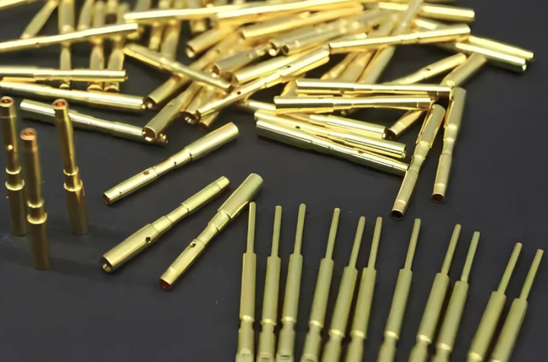
High-precision connector pins fail in the field for reasons a standard diameter check won’t catch.
The parting-off face – that circular cross-section left after the cutoff operation – is where burrs form first, where Ra values quietly climb out of spec, and where poor deburring technology choices create field returns nobody traces back to the machining lot.
Solving section surface finish problems starts with understanding why the end face behaves so differently from the turned barrel – and which deburring approaches are actually suited to the pin geometry.
What is Connector Pin Cross-Section Finish?
Connector pin cross-section finish describes the surface roughness and edge condition at the parted end face of a turned pin – not the OD, but the circular cut surface the parting tool leaves behind.
A pin holding Ra 0.4 μm on its barrel can easily yield Ra 1.0-1.6 μm at the end face, because cutting velocity drops toward zero at the centerline during radial parting. That velocity gap is basically the root cause.
Why the End Face Gets Overlooked
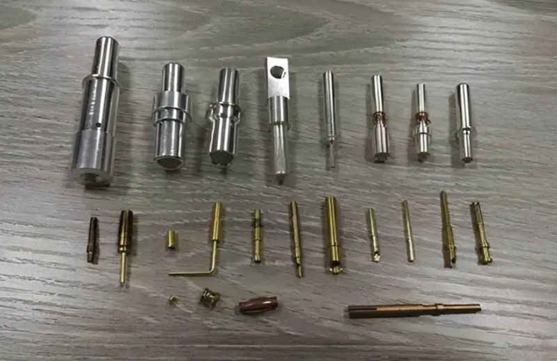
Most connector pin drawings call out surface finish on the OD. Fair enough – that’s where radial contact load sits. But in axial-contact designs (circular MIL-spec connectors, RF coax interfaces, encoder pins), the cut face carries real contact pressure.
Rough peaks deform on first mating, generate metallic debris, that debris migrates into the contact zone. A 15% drift in contact resistance logs as intermittent signal faults, not connector wear. So the connector keeps degrading while someone rewrites firmware.
Surface Finish and Burr Tolerances by Application
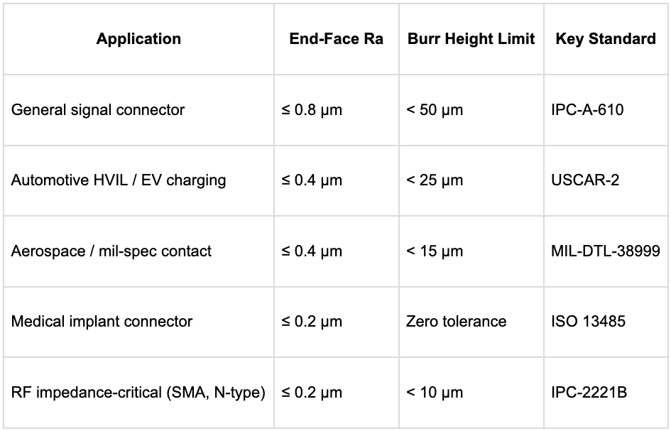
Section surface finish requirements vary widely by end-use. General signal pins tolerate Ra 0.8 μm at the cut face. Medical implant contacts don’t – Ra ≤ 0.2 μm, burr-free, lot-traceable.
EV charging pins and HVIL contacts are a different problem: arc erosion at rough end-face zones accelerates under high-current cycling in ways a static Ra target doesn’t fully capture.
End-Face Ra and Burr Limits by Industry
Material Influence on Burr Character
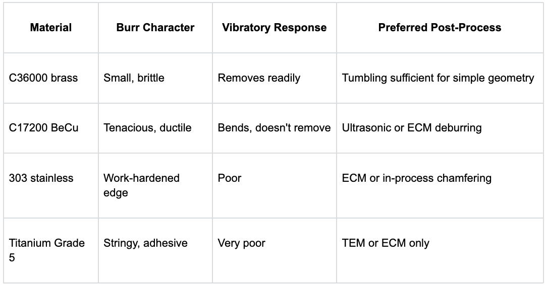
Material choice shapes burr behavior as much as cutting parameters do. C36000 brass produces small, brittle chips – these tumble off readily in vibratory finishing.
C17200 beryllium copper stretches before fracturing, leaving a tenacious burr that vibratory deburring bends sideways rather than removes (don’t quote me on exact mechanism, but the result is consistent).
Stainless steel grades used in medical pins work-harden at the cut face, driving burr height up even with sharp tooling.
How Burrs Form at the Cross-Section
Burrs follow predictable mechanics based on where the cutting edge exits material. Connector pin geometry creates two distinct burr types needing different solutions.
Exit Burrs at the Parting Face
Exit burrs form when the parting tool completes its radial traverse and the remaining web bends rather than shears.
Swiss-type CNC turning handles slender connector pins at aspect ratios up to 12:1 via guide bushing support, controlling deflection through the cutoff pass – Richconn’s production capability data shows what this looks like.
Without that rigidity, the pin flexes, chip geometry goes wrong, end-face burr height jumps unpredictably. OD tolerances hold to ±0.003 mm on Swiss platforms, roughly five microns tighter than conventional turning on slender geometry.
Secondary Burrs in Recessed Features
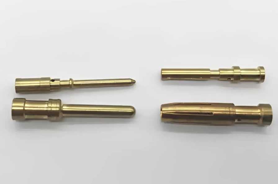
Secondary burrs form at cross-holes, counterbores, and undercuts wherever a tool exits mid-feature – the dangerous kind for socket contacts, recessed where standard tumbling can’t reach.
If one detaches inside a sealed housing, you have a conductive particle free-floating in an impedance-critical assembly. Field return, possibly arc damage, no obvious cause on teardown.
Root challenge: connector pin geometry is awkward for post-process deburring – long, slender (8:1 to 15:1 aspect), external and recessed features on the same part. No single method handles all of it.
Deburring Technology Selection
Choosing the wrong method damages the OD. Choosing nothing creates scrap. For precision connector pin geometries with internal bores or tight end-face specs, the right deburring technology depends on feature accessibility and lot volume.
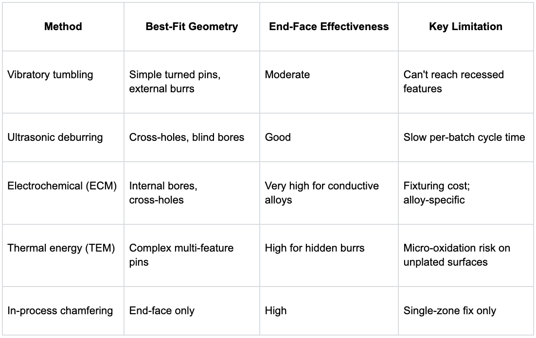
Method Comparison for Connector Pin Geometry
The Two-Stage Flow
For demanding connector pin work, a two-stage approach is generally the minimum. Stage one: in-process chamfering at the parting-off operation – a programmed radius pre-forms the edge before the burr nucleates at full height.
This drops end-face burr height from a typical 30-60 μm range down to roughly under 10 μm on brass and copper alloys, give or take material lot hardness. Stage two covers secondary features through ultrasonic or ECM deburring matched to whether features are accessible or recessed.
When This Approach Doesn’t Make Sense
ECM deburring only justifies its fixturing overhead above roughly 500 pieces per lot – below that, ultrasonic is more practical. TEM carries micro-oxidation risk on unplated surfaces and needs a post-clean step.
Vibratory tumbling alone is insufficient for any pin with internal features or an end-face Ra spec below 0.4 μm.
Basically fine for simple geometry. And if the pin is straight-barrel, no cross-holes, end-face spec above Ra 0.8 μm, the two-stage flow is overkill – standard tumbling plus in-process chamfering handles it. Know which category your geometry falls into before adding process steps.
Bottom Line for Process Selection
Section surface finish problems on connector pins are usually a specification gap, not a machining failure. Match deburring technology to actual feature geometry and lot volume.
Confirm burr condition via metallographic cross-section at the first article stage – optical inspection passes bent-over burrs every time, and those re-lift under load cycling.
Tie the end-face Ra requirement to the contact design load, not just the OD callout. The rest follows from there.
