
When a transmission engineer first runs a new EV drivetrain on a test bench designed for ICE components, something unexpected often happens: the data looks clean, but the drivetrain sounds wrong.
Not broken – just wrong. A faint, high-pitched whine at 3,200 rpm. A harmonic that wasn’t in the simulation. A bearing signature buried under motor noise that the instrumentation wasn’t configured to isolate.
The issue is usually not a bad design. The real problem is that the testing approach was built for a different kind of drivetrain.
The shift from combustion engines to electric vehicles is happening fast, but many testing methods are still based on ICE-era assumptions.
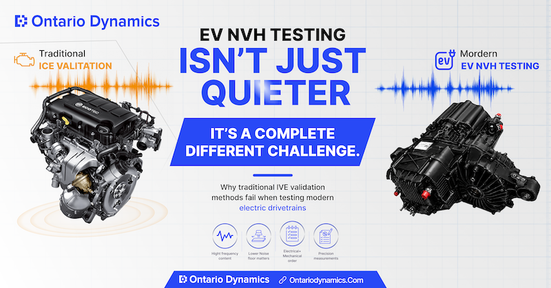
Electric vehicle NVH testing – noise, vibration, and harshness analysis – is not just a quieter version of traditional drivetrain validation. EV systems behave differently, and that changes how engineers need to test them.
In ICE vehicles, engine noise covered many small drivetrain sounds. In EVs, that background noise is gone. Sounds that once went unnoticed can now become obvious inside the cabin.
That means the tools, test rigs, instrumentation, and validation methods all need to evolve to match the realities of electric powertrains.
What the ICE Engine Used to Hide from Vehicle NVH Testing?
An internal combustion engine generates substantial broadband noise, including combustion pulses, valve train clatter, and intake and exhaust acoustics.
This acoustic “floor” is loud enough that many drivetrain NVH issues are often masked by it during normal vehicle operation.
Engineers designing ICE transmissions had to isolate and identify problems against this background. But the background itself masked a lot.
Remove the engine and put in an electric motor, and that acoustic floor drops dramatically. A vehicle that once had a 65 dB ambient noise level at highway speed may now operate at 48 dB. The cabin is quieter. The drivetrain is not.
Gear whine that was imperceptible in a gasoline vehicle becomes the loudest thing in an EV cabin at 80 km/h. Bearing noise signatures that would have been dismissed as within tolerance on an ICE platform are now immediately audible to passengers.
Inverter-switching harmonics – typically in the 8-16 kHz range – can couple into the gearbox housing and radiate as a high-frequency tonal noise that is both physically measurable and deeply irritating to occupants.
This is not a minor calibration problem. It requires a fundamentally different vehicle NVH testing strategy, especially as more manufacturers work with teams experienced in EV drivetrain development and validation to refine acoustic performance before production.
Three Ways Electric Vehicle NVH Testing Differs From ICE Validation
1. The noise floor of your test rig now matters
In ICE validation, test rig background noise was rarely a limiting factor. The drivetrain itself produced far more acoustic energy than any external source. In electric vehicle NVH testing, the opposite is true.
Electric motors are quiet, and the signals you need to capture – gear mesh harmonics, bearing defect frequencies, inverter-induced tonal components – can sit only a few decibels above your instrumentation floor.
This has direct consequences for test rig design. Motor noise from the rig’s drive system must be decoupled from the unit under test.
Mounting arrangements that were adequate for ICE components become acoustic interference sources when the test object is a 200 Nm electric drive unit running at low load.
One approach that has proven effective in practice is contactless magnetic coupling between the drive motor and the test object. By eliminating the mechanical connection at the motor shaft, you remove a primary path for structure-borne noise transmission from the drive into the drivetrain under test.
The result is a cleaner noise floor – typically 6 to 10 dB improvement in the frequency ranges most relevant to EV NVH – which means the signals you are trying to measure are no longer competing with signals you introduced yourself.
This is one of the less obvious decisions that separates a well-specified EV test rig from one that produces ambiguous data. Teams working through this early in their rig design phase – before hardware is committed – can avoid the most common measurement integrity problems.
Many manufacturers now work with specialists in EV product development and validation engineering to address drive isolation, cell acoustics, and DAQ architecture as a unified system rather than as independently sourced components.
2. Electric vehicle motor NVH testing shifts frequency priorities upward
ICE NVH analysis concentrates heavily on low-to-mid frequency content: combustion orders (typically 25-200 Hz for a 4-cylinder at operating speeds), driveline resonances, and structural modes below 1 kHz.
Instrumentation, DAQ sampling rates, and post-processing workflows in legacy test environments are often optimized for this range.
Electric vehicle motor NVH testing requires meaningful instrumentation capability up to 20 kHz and sometimes beyond. Inverter switching frequencies, their harmonics, and the interaction between electrical excitation and mechanical resonance can all produce tonal content in the 5-20 kHz band.
A DAQ system sampled at 20 kHz – which was entirely adequate for most ICE drivetrain work – cannot capture these components without aliasing artifacts.
Beyond the hardware, the analysis approach changes. Order tracking relative to motor RPM is still essential, but you also need to track electrical orders – harmonics of the inverter switching frequency and the pole-pair excitation frequency of the motor – which do not follow the same rotation-based pattern as mechanical gear mesh orders.
Without explicit tracking of both families simultaneously, it is easy to misattribute the source of a tonal complaint.
3. Load simulation requirements change at both ends of the torque curve
ICE drivetrains spend very little time at near-zero torque in real driving. Electric drivetrains do – frequently.
Regenerative braking, low-speed maneuvering, and creep conditions all involve small torques where traditional test rig load control becomes imprecise, and drivetrain backlash and gear rattle become the dominant noise sources.
Conversely, electric motors deliver peak torque from zero RPM, which means your test rig must handle instantaneous torque reversals without introducing its own dynamic response into the measurement.
A rig designed for ICE testing – where torque is delivered smoothly through a rotating assembly with significant rotational inertia – may not have the load control bandwidth to accurately simulate the step-change torque inputs an electric drivetrain experiences in normal use.
This points to a rig design requirement that is not obvious from a component checklist: the control system bandwidth of your load application must be specified relative to the transient load profile of your electric drivetrain, not just its peak torque rating.
What Purpose-built Nvh Vehicle Testing Equipment Actually Looks Like?
Bringing these requirements together into a functioning test bench involves several specific design decisions that experienced teams treat as non-negotiable in EV programs, particularly in advanced mechanical product development and equipment design projects where drivetrain acoustics and validation accuracy directly affect production readiness.
The drive system typically uses a high-speed permanent magnet motor with its own NVH optimisation – low cogging torque, precision-balanced rotor, and quiet drive electronics.
The connection between this drive and the test object uses either a contactless coupling or a torsionally soft coupling specifically chosen to attenuate the drive motor’s noise contribution in the target frequency band.
Instrumentation starts with microphones and accelerometers rated for the full 20 kHz measurement range, placed according to transfer path analysis principles rather than simple proximity to suspected noise sources.
DAQ architecture uses synchronous multi-channel sampling at 50 kHz or higher, with hardware triggering tied to both motor shaft encoders and inverter switching signals simultaneously.
The test cell itself requires acoustic treatment that addresses mid and high frequencies, which means surface materials and geometry choices that differ from traditional drivetrain test cell design.
Semi-anechoic treatment down to 200 Hz is standard for serious NVH vehicle testing work, though full anechoic performance below 100 Hz is often impractical and unnecessary for drivetrain-level programs.
Load control uses a regenerative dynamometer configuration that can apply torque reversals within 20-50 ms – fast enough to simulate real driving events without dynamic artifacts that corrupt the measurement.
Conclusion
Electric drivetrain validation is still a field where many organizations are working from adapted ICE test protocols, retrofitted equipment, and instrumentation systems that were not designed with EV-specific measurement requirements in mind.
The gap between what those setups can reliably measure and what electric vehicle NVH testing actually requires is real, and it shows up in ambiguous test results, extended validation cycles, and – in some cases – acoustic issues that reach production vehicles.
Building the right test capability from the start is not primarily a capital expenditure decision. It is an engineering decision about what level of measurement confidence your validation process actually needs to support.
Companies like Ontario Dynamics are increasingly helping manufacturers bridge that gap through specialized EV validation, automation, and mechanical development expertise.
The author is a mechanical engineer with experience designing custom test rigs and validation systems for automotive and industrial drivetrain applications, including NVH benches, fatigue test systems, and endurance rigs for both ICE and electric powertrain components.
Ontario Dynamics designs and builds custom testing and validation equipment for automotive and industrial manufacturers across North America.
