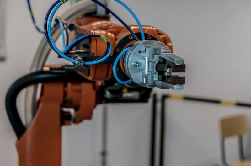
Robots load parts. CNC controls adapt feeds and speeds on the fly. Dashboards stream spindle data in real time. It’s tempting to think the hard work is done by software now, and tooling is just a line item on the purchase order.
But no matter how much intelligence you bolt onto a cell, the cut still happens at a tiny piece of carbide meeting metal. That’s where tool geometry quietly decides whether your smart process actually delivers.
Smart CNC Still Cuts Metal, Not Data
Smart controls and robots don’t change the basic physics of chip formation. Helix angles, rake angles, flute count, edge prep, and corner geometry still dictate cutting forces, heat, chip flow, and surface finish. If those fundamentals are wrong, the “smart” layer spends its time fighting symptoms instead of running a stable, productive cut.
Decisions about end mill selection are still what make or break a process, especially when you’re trying to keep a robot cell running unattended.
You can see this in how a lot of “Industry 4.0” projects are structured. Labs like NIST’s digital twin and monitoring environments pair robot arms, CNCs, and metrology in the same setup so they can study how AI and sensors adjust machining conditions in real time.
Even there, the work assumes that the underlying cutting tool is appropriate for the job – AI-enhanced analytics help squeeze more out of a fundamentally sound process, not rescue one built on poor geometry choices.
Efforts around AI-enhanced monitoring in manufacturing processes focus on detecting chatter, overload, and drift; tool shape is still the baseline that determines how often those problems show up.
Geometry Is the Language the Machine Really Speaks
Look at a typical high-mix job shop running automation: one cell might machine stainless brackets in the morning and aluminum housings in the afternoon. On paper, the CNC parameters change via program, and the robot doesn’t care what’s in the gripper. On the floor, though, geometry choices define how forgiving that setup really is.
Research on machining quality shows that small changes in edge radius, rake angle, and helix angle can significantly alter cutting forces and surface roughness, even when material and parameters stay the same.
A recent study on machining quality indicators and tool parameters found that optimizing tool micro-geometry reduced both cutting forces and surface roughness, directly improving consistency and tool life across passes and parts. That’s exactly the sensitivity that will either support or undermine stable, robot-fed production.
Practically, this means you can’t treat “a 10 mm carbide end mill” as a single category in a database. The same nominal size with a different helix angle or flute count behaves like a different tool.
For example, a high-helix, polished 3-flute is far more forgiving in aluminum pockets than a 4-flute general-purpose design; the wrong choice might push chip packing onto the robot operator’s shift, no matter how advanced your monitoring stack is.
Where Robots Meet Cutting Edges on the Shop Floor
Once robots enter the picture, process robustness becomes more critical than raw cycle time. A human operator might hear a slight squeal and back off; a robot just keeps loading parts. Tool geometry is your first line of defense against those silent failures.
If you’re profiling hard stainless, a small corner radius relieves stress at the tool tip and reduces the chance of chipping. That doesn’t just extend tool life; it also keeps dimensional drift under control between scheduled offsets.
In a robot-loaded line, that’s the difference between a stable run of fifty parts and a pile of rework because a sharp corner chipped halfway through the shift.
The same story plays out with flute count and chip space. In tight pockets where chip evacuation is tricky, a 2- or 3-flute design with adequate chip gullet gives your high-feed strategy room to work.
A 4-flute with limited chip space might look efficient on a spreadsheet but quietly builds heat and chip recutting until the process tips into chatter. Robots don’t compensate; they just reveal whether your geometry choices were realistic.
Practical Ways to Keep Geometry in the Loop
If you’re already investing in smarter CNC and robotics, the easiest upgrade is how you formalize tool geometry decisions.
Start by standardizing “tool families” by material and operation, not just by diameter. For aluminum, that might mean explicitly specifying high-helix, polished 3-flute tools with a small corner radius for roughing and finishing.
For hard steels, you might define a low-helix, multi-flute design with specific edge prep and coatings. Make those choices explicit in your tooling database instead of letting programmers pick whatever appears first in the catalog.
Next, tie geometry decisions into your process approval work. When a new part is routed into a robotic cell, review not only feeds and speeds, but also helix angle, flute count, and corner geometry on every primary cutter.
Ask simple questions: will this flute configuration clear chips in this pocket? Is the corner design robust enough for the programmed engagement? Does the edge prep match the material and coolant strategy?
Finally, feed what you learn back into your standards. When a particular tool geometry consistently delivers better surface finish or fewer overload alarms, treat that as a rule for similar parts, not a lucky one-off.
Over a handful of programs, you’ll end up with a library of geometries that naturally support the automated behavior you’re trying to scale.
Conclusion
Smart CNC controls and industrial robots can only optimize the process you give them; tool geometry still defines the cut they’re optimizing. If you treat geometry as a first-class design decision – not an afterthought – you’ll get more out of every sensor, robot, and algorithm you put on the shop floor.
