Industrial robots are sold as complete systems, but under the housing, they are assemblies of individually machined parts. Every joint, every actuator mount, and every end-of-arm tool starts as a block of metal on a CNC machine before it becomes part of a functioning robot.
This matters to robotics companies because the quality and lead time of these machined components directly affect how quickly a robot moves from prototype to production. A bearing housing that is 0.05mm out of spec creates play in a joint that compounds across the kinematic chain.
A gearbox casing with a poor surface finish wears faster under load. These are not theoretical problems. They are the kinds of issues that delay product launches and drive up warranty costs.
For companies that do not machine parts in-house, sourcing these components means finding suppliers who can hold tight tolerances in the specific materials robotics demands, mainly aluminum alloys, hardened steels, and sometimes titanium.
Online CNC machining platforms have made this easier by allowing engineering teams to upload CAD files and compare quotes from multiple verified manufacturers, but determining which components require the most attention during sourcing remains the engineer’s responsibility.
The seven components below are present in virtually every industrial robot. Each one has specific machining requirements that affect performance, and understanding those requirements helps both when designing for manufacturability and when evaluating potential suppliers.
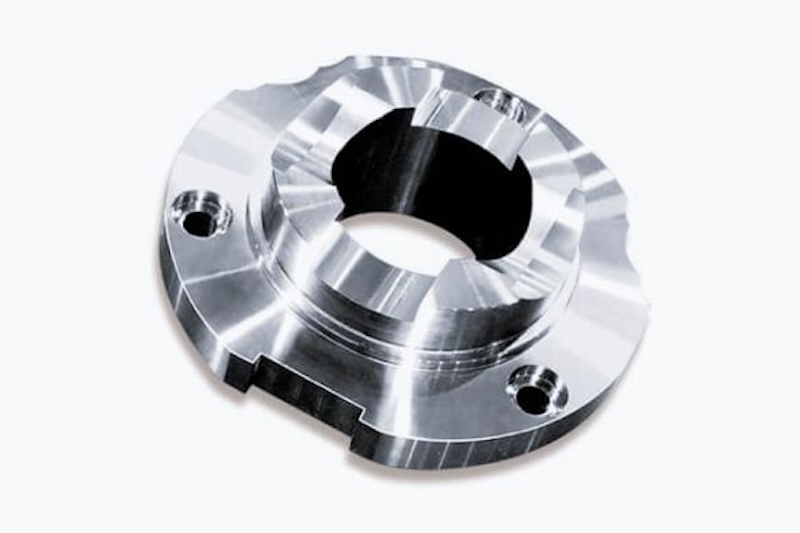
1. Joint Housings
The joint housing is the structural shell that encloses the bearings, gears, and motor at each axis of rotation. It carries the full load path between adjacent links, so it must be stiff, dimensionally stable, and precisely bored.
Most joint housings are machined from 6061-T6 or 7075-T6 aluminum to reduce weight, though larger industrial robots sometimes use ductile iron or steel castings that are finish-machined on a CNC mill.
The critical features are the bearing bores, which typically need to be held to within ±0.01mm to ensure proper bearing preload and alignment. If the bore is oversized, the bearing has radial play. If it is undersized, the bearing seats are too tight and generate heat under continuous operation.
These parts almost always require 4- or 5-axis milling because the bearing bores, mounting faces, and cable routing features are on multiple sides of the part. A shop with only 3-axis machines will need multiple setups, increasing the risk of positional error between features.
2. Gearbox Casings
Every axis on an industrial robot has a speed reducer, usually a harmonic drive or cycloidal gearbox, and that reducer needs a casing that maintains precise alignment between the input and output shafts.
The casing also acts as the structural connection between the motor and the joint, so it must handle both torque loads and the reaction forces from the gear mesh.
Gearbox casings are typically machined from aluminum or steel, depending on the load class. The bore that seats the wave generator or eccentric cam needs surface finishes below Ra 0.8µm and concentricity within a few microns of the output bearing bore.
If these features are misaligned, the gearbox runs rough, generates excess heat, and wears prematurely.
Robotics companies that use off-the-shelf harmonic drives from Harmonic Drive Systems or similar suppliers still need custom casings because the gearbox must integrate with a specific motor, encoder, and joint structure.
This is one of the most frequently outsourced machined components in the industry because few robotics startups have the grinding and precision boring equipment needed to finish these parts in-house.
3. Motor Mounting Plates and Flanges
The motor mount connects the servo motor to the gearbox and joint structure. It seems like a simple part, a flat plate with a bolt pattern and a central bore, but the tolerances on it determine whether the motor shaft aligns properly with the gearbox input.
Misalignment between the motor and gearbox, even by a few hundredths of a millimeter, creates vibration that the robot’s controller has to compensate for. In high-speed pick-and-place applications, this vibration limits cycle time because the controller needs extra settling time after each move.
In collaborative robots that operate close to people, vibration also affects the accuracy of force-torque sensing at the joints.
Motor mounts are straightforward CNC milling jobs, usually 3-axis work in aluminum or steel. The critical dimension is the concentricity of the pilot bore relative to the bolt pattern. Good drawings call this out with GD&T position tolerances of 0.02mm or less.
It is a simple part to machine, but shops that do not pay attention to fixture alignment will produce parts that technically pass individual dimension checks while still being out of position as an assembly.
4. End Effector Interface Plates
The end effector interface, also called the tool flange, is the plate at the end of the robot arm where grippers, welding torches, dispensing heads, and other tools attach. ISO 9409-1 defines a set of standard flange patterns for this interface, and most industrial robots follow one of those standards.
The machining requirements are driven by the fact that this plate is the datum for everything the robot does. If the flange face is not perpendicular to the last axis of rotation, the tool center point shifts with every rotation, and the robot cannot hit its programmed positions accurately.
Flatness and perpendicularity on the flange face are typically specified within 0.01mm to 0.02mm.
These are usually turned parts finished on a CNC lathe with live tooling for the bolt holes and dowel pin holes. The dowel pin holes are the most important feature because they locate the tool relative to the flange, and they need to be reamed to H7 tolerance or tighter.
A sloppy dowel fit means the tool shifts slightly each time it is reinstalled, defeating the purpose of the locating feature.
5. Link Structures (Arm Segments)
The link structures are the arm segments that connect one joint to the next. They define the robot’s reach, payload capacity, and stiffness. In smaller cobots, these are often aluminum extrusions or cast parts that are finish-machined.
In larger industrial robots, they are typically CNC-machined from aluminum billet or fabricated from welded steel and then machined to final dimensions.
The machining on link structures focuses on the joint mounting interfaces at each end. These faces must be flat and parallel to each other within tight tolerances because any angular error between joints accumulates along the arm.
A 0.1-degree tilt at one joint can translate to several millimeters of positional error at the tool tip, depending on the arm length.
Weight is always a concern with link structures because every gram in the arm reduces payload capacity. This is why many robotics companies design links with internal pocketing, thin walls, and organic shapes that remove material without sacrificing stiffness.
These features push the machining toward 5-axis milling with long-reach tooling, which increases the cost per part but improves the robot’s overall performance-to-weight ratio.
Tool geometry choices during these operations directly affect surface finish and dimensional accuracy, especially on thin-walled pockets where chatter is a constant risk.
6. Bearing Seats and Shaft Interfaces
Industrial robots use cross-roller bearings, angular contact bearings, or thin-section bearings at each joint, and these bearings need precisely machined seats to function properly.
The bearing seat is the cylindrical surface that the bearing outer ring presses into, and the shaft interface is the surface that supports the inner ring.
The tolerance requirements are set by the bearing manufacturer. A typical cross-roller bearing for a robot joint calls for an H5 or H6 bore tolerance on the housing side and a j5 or k5 shaft tolerance on the inner ring side. In practice, this means the machined bore needs to be accurate to within a few microns.
CNC turning or precision boring is the standard process, followed by grinding if the required tolerance is tighter than what the lathe can hold.
Getting these fits wrong has immediate consequences. A loose housing fit allows the outer ring to creep, generating heat and wearing the bore. A tight shaft fit can preload the bearing beyond its design limit, reducing service life.
Both failure modes manifest as increased joint friction and, eventually, positioning errors that the robot’s controller cannot calibrate out. Precision components like these are often the difference between a robot that holds spec over thousands of hours and one that drifts out of calibration within months.
7. Encoder and Sensor Mounting Features
Accurate position feedback is what separates an industrial robot from a simple actuator. Optical or magnetic encoders at each joint measure rotation to resolutions as fine as 0.001 degrees. But that resolution is meaningless if the encoder is not mounted so it remains aligned with the axis of rotation.
Encoder mounts are small features, sometimes just a bored pocket and a set of tapped holes on the back side of a joint housing. But the position and concentricity of the bore that holds the encoder reading head relative to the encoder disk or ring must be controlled to within ±0.01mm.
Any eccentricity between the reading head and the disk introduces a once-per-revolution sinusoidal error in the position feedback, which directly degrades the robot’s repeatability.
Force-torque sensors, proximity sensors, and limit switches also require machined mounting surfaces. These features are easy to overlook during design because they are small, but they often cause the most problems during assembly if the machining is not precise.
Why These Components Matter for Robotics Sourcing
All seven of these components share a common thread. They require tolerances tighter than those for general-purpose machining but not so extreme that exotic equipment is needed.
The sweet spot for most robotics parts is ±0.01mm to ±0.025mm, which falls within the capability of a competent CNC shop with well-maintained equipment and experienced machinists.
The real challenge for robotics companies, especially startups and mid-size firms scaling production, is finding suppliers who can hold these tolerances consistently across batches.
A shop that hits spec on the first five prototypes but drifts on a production order of 500 creates a quality problem that surfaces only after the robots are already assembled. This is where supplier verification, equipment audits, and structured quoting processes matter more than the lowest per-part price.
Robotics engineering teams that invest time in understanding the machining requirements behind their designs will make better sourcing decisions, write better drawings, and spend less time troubleshooting assembly and performance issues downstream.
