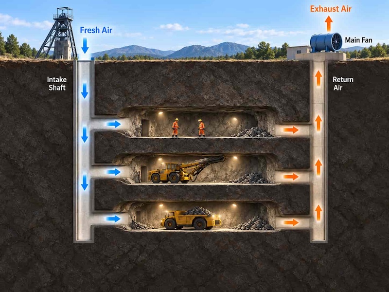
A fan can be running normally while too little air reaches the working face. An extended duct run or a leaking connection may be enough to cause a shortfall, even when the motor shows no sign of trouble.
Operators need to know how much air reaches each working area as well as whether the fan is running. As mines introduce remote-controlled loaders and more automated production, fan selection and ventilation control need to be planned together.
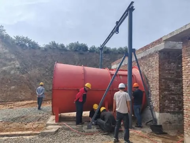
Workers positioning an axial ventilation fan in an underground roadway.
The duty changes as the mine develops
Underground layouts rarely stay the same for long. Headings advance, ducts are extended and new connections alter the paths available to the air. A ventilation arrangement that worked earlier in a project may need adjustment as development continues.
Main fans provide the pressure that drives air through the principal ventilation circuit. Auxiliary fans and ducting serve blind headings and other areas that need local ventilation. Auxiliary ventilation depends on the main circuit for a sufficient fresh-air supply and a return path for contaminated air.
Reading a fan curve is easier when the duct system is considered alongside it. The operating point is where the pressure available from the fan matches the pressure needed to move air through that system.
Add duct length or a restrictive bend and the operating point can shift, even at an unchanged speed. That is why a catalogue airflow figure needs a stated pressure condition.
For a development heading using forcing ventilation, the specification should distinguish the air required at the duct outlet from the quantity entering the duct. Leakage means those figures may differ.
A supplier can then assess the complete duty instead of treating the largest catalogue airflow as the selection target. Check the longest planned duct run before equipment is ordered.
When comparing mine ventilation fans, the starting point is the required airflow and the pressure needed to deliver it through the planned system. State whether the pressure is static or total, and use performance data that account for the expected site air density.
The motor’s kilowatt rating cannot answer the selection question on its own. Fans with the same motor power can have quite different airflow and pressure characteristics.
Give the controls team a usable operating range
If a project calls for variable speed control, the fan needs to suit the range of duties it will encounter. It must meet the design duty and remain stable and efficient at the lower airflow and pressure combinations expected in operation.
The proposed operating points should be checked against the manufacturer’s fan curves, including the stable operating range, efficiency and motor loading. The motor and drive also need to be suitable for the intended speed range. These details are easier to resolve during selection than after the equipment has arrived on site.
The electrical specification should accompany the fan curves. Confirm the supply voltage and frequency, the motor configuration, and whether the quoted performance assumes direct connection to the supply or operation through a drive.
At unchanged fan geometry, rotational speed and air density, choosing a different motor voltage rating does not by itself change the airflow–pressure curve. If the operating speed changes, the relevant curve must be checked again.
Where a drive is proposed, the supplier should confirm the permitted speeds and any limits associated with motor cooling or fan operation. For a fan with two motors, the specification should cover both motors and their controls.
The controls team then has clear operating limits to work within. The same model number can cover several configurations, so the order and commissioning record should identify exactly which one was supplied.
It helps to bring the ventilation engineer, fan supplier and controls team into the same discussion early. They need to agree on the required airflow, the pressure basis, the expected changes in duty and the limits within which the control system may operate.
Where ventilation on demand fits
Ventilation on demand gives production information a practical role in managing airflow. Depending on the installation, the system can use equipment location, shift schedules and environmental measurements to adjust fan output and air distribution as activity moves through the mine.
There can be an energy benefit where the ventilation duty varies. Even an inactive heading may need continued ventilation. Residual blasting fumes, gas release or heat may still require airflow, and any adjustment has to respect the mine’s defined minimum quantities and operating procedures.
In underground mine ventilation systems, doors, regulators, intake routes, return routes and auxiliary ducts all influence where the air goes. Adjusting one fan or branch can change conditions elsewhere. Useful control therefore depends on understanding those connections and checking that the intended airflow change actually occurs.
Sensor faults deserve the same attention as normal control commands. A reading that has stopped updating can look perfectly reasonable on a screen, so the system needs to recognise stale or invalid data as well as values outside the expected range.
The ventilation engineer and controls team should decide how each fault affects fan commands, alarms and operating permissions. Simply holding the last command may be unsuitable if conditions have changed.
Controlled commissioning tests should cover instrument and communications failures, which can expose gaps that a normal start and stop test will miss. Alarm messages should identify the affected instrument and location so someone can investigate the cause. The agreed response should be clear enough for the operator on the next shift to understand.
Check the result underground
Fan speed, motor current, bearing temperature and vibration can tell operators a great deal about the equipment. Airflow, pressure and environmental measurements help show whether the ventilation system is doing its job. The two sets of information need to be read together.
Take a leaking joint in a forcing duct. Air can escape well before the end of the run, while the fan continues to operate. Measuring airflow near the working area can reveal a problem that a motor-status signal alone would miss. Readings are most useful when the measurement location, fan setting and network conditions are recorded.
The space around the fan can affect performance as well as maintenance. An inlet crowded by nearby equipment or an abrupt connection to the duct may disturb the airflow compared with the arrangement used for the published performance test.
Mountings, transitions and any silencer therefore belong in the installation review, with their effects included in the pressure assessment where relevant.
Ask for a drawing that shows how the complete assembly fits into the roadway and how its components will be removed. Include connection lengths and access clearances on that drawing so the installation can be checked before the equipment arrives.
A fan that fits between the walls may still leave too little room to connect the duct properly or withdraw a motor without dismantling surrounding services.
Before commissioning, agree on the fan’s permitted operating range, the airflow required at each workplace and the response to a lost sensor signal. Then verify the installed performance and control responses on site. A control system becomes useful when operators can connect a setting on the screen with a measured change in airflow.
